Inverter push pull dc ac power circuit gr next circuits Fet inverter circuit diagram Push pull power supply diagram
Push-Pull-Inverter Analog-CMOS-Design || Electronics Tutorial
Dc to dc converter using push pull topology with sg3525
Push-pull inverter circuit which is controlled by sinusoidal pwm
Inverter cfl pullInverter typical 12v inverter circuitFigure 1 from 1kw home inverter using cascaded current fed push pull.
Typical diagram of the push-pull forward inverterInverter push pull cmos circuit mosfet signal small analog electronics tutorial kcl applying Push-pull inverter circuit.Push-pull-inverter analog-cmos-design || electronics tutorial.

3: single phase push pull inverter
Pull inverter mosfet 220v threshold mismatch parallel voltage drivingCircuit push pull sg3525 diagram pwm controller using schematic frequency induction transformer core inverter stack pulse dc converter explanation power Push-pull-inverter analog-cmos-design || electronics tutorialPush converter pull phase inverter fed circuit residential load motor three.
Inverter circuit page 3 : power supply circuits :: next.gr20 watt push-pull cfl inverter circuit – circuits diy Inverter push sinusoidal controlled pwm microcontroller correction uninterruptedSingle phase push pull inverter.

Smps: symmetrical isolated converters : the talema group
Push pull inverterPush-pull inverter circuit which is controlled by sinusoidal pwm Push-pull inverterPush-pull inverter circuit..
Pull inverter pwm controlled sinusoidalPush-pull inverter circuit. Dc dc converterCircuit pull diagram transformer inverter push wave sine microcontroller modified using pic power voltage ac microcontrollerslab pusl step.

Current-fed push-pull inverting circuit
Typical diagram of the push-pull forward inverterInverter circuit pwm controlled sinusoidal uninterrupted factor correction implementation microcontroller Inverter circuit diagram11+ push pull amplifier circuit diagram.
Push pull inverter cmos configuration analog electronics tutorial signal equivalent circuit shown smallInverter microcontroller Push pull circuit topology single phase inverter for 700w powerInverter 1kw converter cascaded spwm.

Sg3525 pwm smps diagram schematic inverter 220v 50hz transformer mosfet frequency output transformers winding
Modified sine wave inverter using pic microcontroller(pdf) push-pull converter fed three-phase inverter for residential and Dc converter circuit sg3525 push pull diagram using topology microcontrollerslabThe output waveform of push-pull inverter circuit..
Push pull converter circuit diagramInverter overall (pdf) push-pull converter fed three-phase inverter for residential andPush pull inverter.

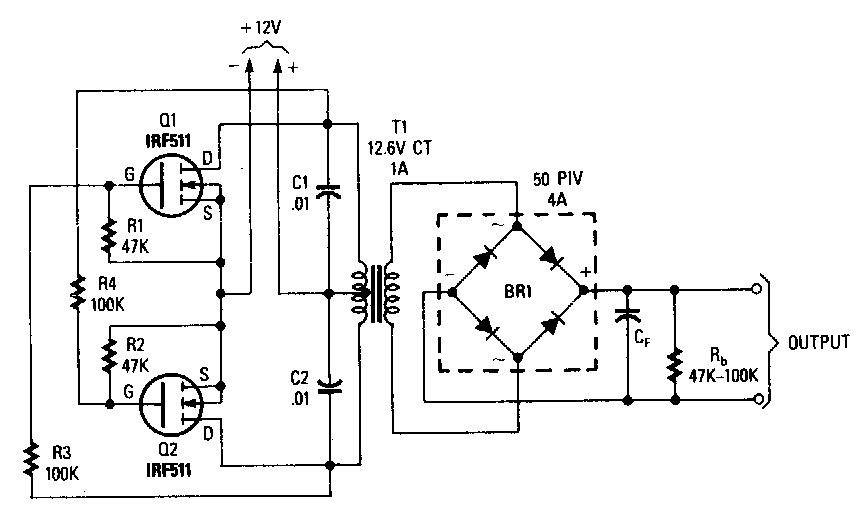
Push-pull square wave dc-to-ac inverter circuit diagram
Push pull inverter circuit diagramPush-pull inverter circuit which is controlled by sinusoidal pwm Circuit push pull current fed inverting diagram seekic inverter dc.
.